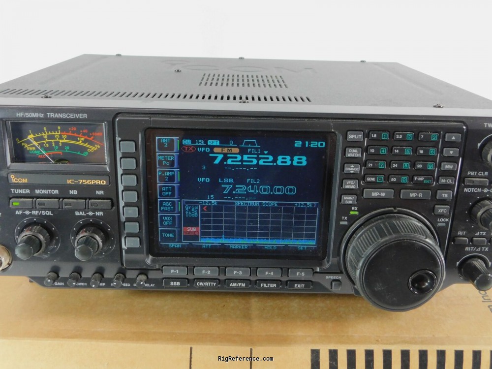
- Icom ic 756 pro ii manual manuals#
- Icom ic 756 pro ii manual apk mod#
- Icom ic 756 pro ii manual mod#
- Icom ic 756 pro ii manual serial#
While the transistor can be replaced, the coil is now obsolete. In the case of the PRO radios, this results in either a blown transistor or open inverter coil. This puts unnecessary stress on the voltage inverter circuit. Is the display in your PRO series radio starting to dim? Does it take five or ten minutes or more to reach full brightness? After this time, the tube usually only reaches half its original brightness. Note 5: Transmitting is possible continuously from 1.QRZ Forums. Note 4: Transmitting below kHz not recommended. The following notes apply to operating range: Note 3: TX power drops out below kHz due to band filter. After successful modification, the following notes apply: Note 1: Diodes and remain in place. Version Number: 2 on original packing box, for USA market.
Icom ic 756 pro ii manual serial#
I think it's an older PRO, serial Note: 1 Experiment at your own risk.
Icom ic 756 pro ii manual mod#
The mod suggested above enables transmit from 1. No observable reduction in operation upon firing it up. Left diodes connected and "hanging" by other end. Heated one end, used very small blade knife to lift desoldered end. Diodes on my Ver 2 were instantly identifiable. Easy to gently "rock" it back and forth, pops right off. CPU box is connected to mother board via two multi-conductor connectors. I followed the suggested steps for making P continuous Xmit from 1.īottom cover removed by 10 screws 6 on bottom and 4 on sidesno need to remove feet. If there's something going wrong I've no responsibility This info is from a Icom-infosheet. When you have a version " 02" : remove diodeand ! If you can't find out the version of your PRO 02 or 03look at the topside of the box. You have to remove 3 small diodes located on the left side of number "" diodesand when you have a version " 03" Icom ICPRO.

You can see on the right of the row the number ""that diode is already missinghi. You have lift the dsp-box with care! After removing the dspyou can see a row of diodes with some spaces. When you removed the cover and you have the backside of the PRO facing youyou can locate the dsp-box on the left-side the shiny-box. You have to remove the bottom cover of the PRO. R is the proper adjustment point but you need to make sure you follow the proper procedure per the service manual. You have to look in the service manual to find out what number is correct.
Icom ic 756 pro ii manual apk mod#
Thunder vpn apk mod full premium unlocked There are only numbers marked on the board. Looking on Main board for the tiny potentiometer at the bottom side of the transceiver. Newer Post Older Post Home.Open the bottom lid of the radio.

The end result was awesome One of the pics here is the filter as modeled in software, the violet curve is before mods, the white curve is after mods. This moves the knee of the filter from 5.
Icom ic 756 pro ii manual manuals#
I checked the manuals and board layouts against each other, and while the filter units in the standard and Pro II are physically a little different, the circuit was the same. He came up with a few capacitor changes to alter the upper end of the filter response to fix the problem in the Pro II. He had access to some filter design software, and modeled the 80m filter to see where the problem was. Another ham I was talking to on the internet had the IC Pro II and modified his for 60m coverage as I did, and had the same problem with low output power. Here's the info for the first phase of the modification I found that the band matrix is setup to use the 80m low pass filter up to 6. First, the transmitter has to be opened up for general coverage operation.


 0 kommentar(er)
